Deltesian - Designing & Testing Replacement Rod Arms

Finally got the big bed printing! One of the next steps is to replace the Delta Rod End Arms with Arms w/ Ball Bearings. 

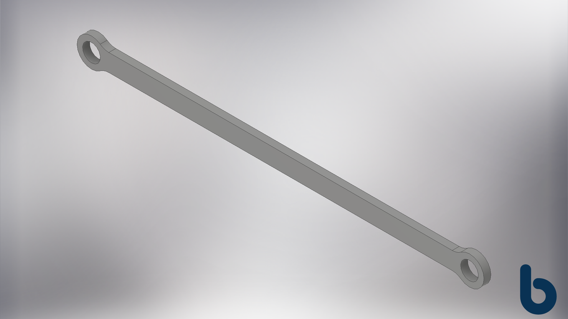
217mm Printed Ball Bearing Arm - Inventor.png

Basic, First Design. I don't have much experience with long thin printed parts, so I'm starting with a very simple design. 217mm center to center with a 10mm x 4mm shaft cross section.

1st Test Rod Arm Printed

2018-01-05 22.10.21.jpg

Finished Part off the Printer

Press Fit in the 623ZZ Bearings. These are 3mm ID X 10mm OD x 4mm THK. 

These are interference fit, but the modeled hole is Ø10.2mm due to printed holes being slightly smaller.

Printed Arm Installed. I'm surprised it has so much play. If I had to guess, it's about 1/4th the stiffness of the original carbon fiber rod. 

Need to look into how to print a more rigid structure.

Checking the Stiffness of the New Arm and Effector.

My notepad entry immediately after: Expected it to be Stiffer, not sure if better or worse that Delta Rod Arm.

Edit: This is the 2 Wall arm.

Figured out why the arm was so flexible: Cura was only slicing with 2 walls instead of 4. It appears to be some bug in how I configured the Deltesian as a custom machine. I created a new machine type in Cura, set it as a Delta Kossel Mini and then set the bed size to 200x420mm and Cura sliced the model with 4 walls as intended. 

The 4 walls are important b/c (1) the holes for the bearing are designed to be solid plastic when printed, i.e. no infill & (2) those layers are what give the arm beam stiffness, like an I-Beam. 

FEA testing in Inventor

I need to get a better idea on some of the failure modes of a shape like this arm so I running some analysis of the arm under different loading conditions.

It's Important to note: 

  • I'm using small load conditions to understand which design element is the weak link.
  • I'm not validating a design here. I don't know enough to call this anything other than my first best guess. I'm the kid taking apart his toys trying to understand how they work.
  • I'm only showing the Load Condition and Von Mises Stress images. I have full readout...400 pages of it, not exactly page scrolling stuff. 
  • If you know more about FEA and plastic/printed plastic deformation, please let me know, I'm probably missing something.

Cantilever Loading

Fixing the right bearing seat and loading the left shows a build up of stress near the shoulders on the right. This will never happen with the bearings mounted but its interesting to see.

Tensile Loading

Result_0_1.png

Applying a Force pulling the two bearing seats apart, results in some interesting deformation in the left bearing seat. The only the right seat does not look like the left, b/c the software thinks it's fixed in place.

Out of Plane Loading

Applying a force out of plane--in relation to the Deltesian Effector--show stress concentrations near the right bearing seat. This sort of loading is possible with the Deltesian. I need to experiment and research some better ways to design the part to increase the strength and stiffness under these conditions.

torque loading

Applying a moment to the left bearing seat is interesting(?). I'm not exactly sure what to make of this other than: "Long Thin Thing Twists - More on that at 10.It's obvious in retrospect but had to check anyways.


2 Walls vs 4 Walls

2nd Printed Rod Arm with 4 Walls Installed.

This is where stuff gets weird. In the hand, it feels less stiff than the 2 wall version. It doesn't make sense, which is why I'm confused. 

The really odd part happens when I attach the arm and see how it feels on the machine...

Watch the Effector (blue thing) when I try and *roll* it left to right. Its the last action in both clips.

I had to post the 1 New Arm vs 2 New Arm videos side by side so you can see what I felt, which I questioned if I was imagining things:

Swapping the 2 lower Rod End Arms out for the Roller Bearing Arms appears to have reduced whatever small amount of roll the Effector was free to do. 

Typing this out it, I realize it seems obvious but I did not expect it to make that big a difference.


take aways

  • Didn't expect the arms to stiffen the effector the way it did.
  • I don't fully understand where the slop was that allowed the rolling motion.
  • Need to test further the difference between 2vs4 walls. Apparently, I don't fully understand where thicker walls are beneficial.  
  • FEA gave me some ideas on how to modify the geometry to stiffen and reinforce things.
  • Is the flex in the arms okay? Need to answer that.

Calling it quits at that. It's a lot to think about.


Personal note: I want to make this a thing, to keep myself documenting the process. I'm not diligent enough at these sort of things but I really enjoy it when I do it so, here's hoping.

-bornity

Work In Progress - DSLR Quick Mount

I'm adapting the 8020 Quick Mount, as seen on the Constant Force Joints page, for a mounting a camera with a typical 1/4-20 mount. I need to swap the 5/16-18 bolt for a 1/4-20 bolt and redesign the Constant Force Washer and Thrust Washers for the smaller bolt.

 I thought it could be an easy swap but realize the pass-thru bolt would need to be captured when you remove the camera. I've added an threaded knurled thumb knob which feels nice when threaded into the camera.

There are still some tweaks needed but it's coming together. Should be ready to release it soon. 

As a side note, the Neon Yellow PLA used above, kept randomly stopping extruding. 3 hours of messing with temps, speeds and accelerations, I realized the filament had looped under itself and was binding after a few full turns of the filament roll. I pulled out a few feet and found the loop and pulled it out from itself and it fixed everything. Oh well, what else you gonna do.

-bornity

Constant Force Joint Write up is Complete

Wow, 3 days to do my full write up of the Constant Force Joints. A lot of time was getting 3D models printed to have a sufficient demonstration piece to show of the the joints. It was a project just to show off a project. But I wanted a detailed write up b/c I keep using these joints in everything and having a page to point people too for future projects is invaluable.

I'd like like to get a math section or page for the Joints put together b/c there are some interesting things happening with the Axially loaded Deep Groove Ball Bearing and the Friction between the Thrust Washers and Linkages. 

Overall very happy with the presentation but I'll probably end up re-writing half the copy when I've had a good night's sleep. Oh, and the phone stand is pretty cool.

-bornity

Router Lift attached to Table Saw

Over the weekend, I joined up the Router Lift to my router table/table saw setup. The table saw itself pivots on a really nifty 608 ball-bearing pivot joint I came up with. I did have to cut a hole in the top of the cabinet to fit the anti-backlash plate but other than that I'm pleased with the motion.

The dust collection system I have for the table saw has been a long time coming and I'm really happy with it. I'll do a full write up at in the future. I think there are some really cool techniques that might inspire other people.

The router table surface is a 1/4" A36 Steel plate, and 8020 1010/2010 Aluminum Extrusion for the frame. 

Anyways, just a preview for now.

-bornity

3D Printed Dewalt 618 Router Lift First Look

Finished uploading some shots of the work in progress router lift. I still have to refine a lot of the parts and work on add a drive rod to allow changing the height from above the table surface. For now its something functional I can get feedback on.


-bornity

Reverse-Engineering a Sewing Machine Gear is up

Finished the write up for the custom gear I made for a serger. Fun little project. You can find it in the project section. I still need to add the gear to thingiverse.com but the Lifter Arm is there. 

-bornity

Hello World.

Time to start putting this stuff out there for people to see. I've got a lot of cool projects to share that I just need to write up so you can expect to see more of them in the future. 

-rob/bornity