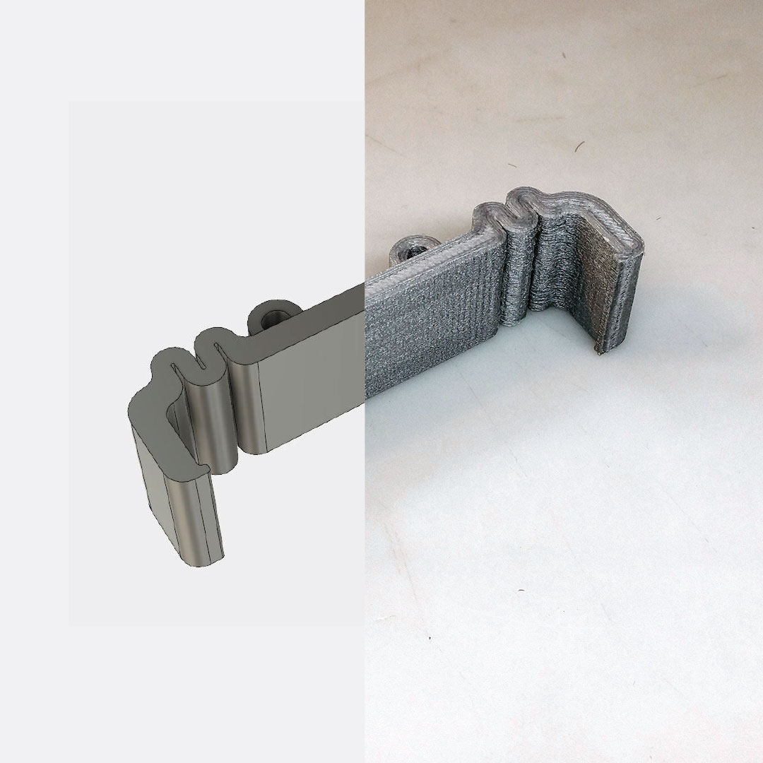
Tutorial: Designing a 3D Printed Phone Spring Clip in Fusion 360
Parametric modeling is one of the most powerful modeling techniques. It's intimidating at first but with practice becomes second nature. Fusion 360 is a accessible program to get into parametric modeling.
I wanted to show the benefits of a parametric model. A great test bed is a phone/tablet mount, that relies on a printed spring element.
One of the most frustrating things as a designer is understanding why certain design decisions were made. Why is that fillet 2.5mm? Why is the bolt pattern 0.385"?
I hope in this write up, I can explain, why I came to certain decisions and give you some ideas to consider in your next design.
Files:
Get the Galaxy Note 4 Phone Clip: Here on Thingiverse.
Get the Fusion 360 file: Here on A360.
Uses components from my: Constant Force Joints.
Clip Demonstration
The 3D printed spring element allows for one handed mounting and removal. The spring gives enough flex to allow the phone to pass the lip and clip into place.
Different size clips for devices with and without cases
The mounts shown here use my Constant Force Joints. Different variations are easy to configure with a parametric model in Fusion 360.
The spring elements can be used in many applications once you understand the basics of modeling them.
LG G3, Galaxy Note 4 and Samsung Tab 4 7".
Measuring my device width and thickness
I used a Galaxy Note 4 to model the base clip.
Measuring the width with a pair of digital calipers. Here, MeasuredWidth = 81.45mm.
Measuring the thickness accurately is a little more difficult. I used a steel ruler to span the face of the case.
I measured the thickness of the ruler and zero'd the calipers.
Measuring the thickness of the phone. Remember the thickness of the ruler has been zero'd out. Here: MeasuredThickness = 11.40mm.
Fusion 360 Modeling Timelapse
Timelapse of the modeling process. I took screen-caps every 5 secs using an automated task and then combined them into a video. The gif(webm) is in ~1080p. You can fullscreen and pause at any frame if you're unsure of a step.
fusion 360 Modeling Process
Cross Section Sketch
I set up a sketch for the measured dimensions. I arrived at the +/-1mm value in the image through trial and error. Please know this may change depending on your printer and device.
Phone Clip frame Sketch
Creating a new sketch, Phone Clip Frame Sketch, I project the lines from the Cross Section Sketch. I create the basic lines to form the outside of the frame and then dimension them.
Extrude Frame Clip
I use 12.7mm/0.5in because this will interface with the Clip Mount.
Cutout Sketch for Spring Geometry
I created a sketch to remove half the Frame body and a section where I will put the spring. I will mirror the everything at the end.
Project Phone Clip Frame Body
I project the cross section of the frame body.
Define Regions to Remove
I remove the lower half the Frame body and a section where I will put the spring. I will mirror the everything at the end.
Spring Geometry Sketch
New sketch for spring geometry.
Spring Geometry Design Considerations
I've outlined that major dimensional considerations you should make when designing an element like this. I want the spring element to print as a solid to ensure it flexes correctly. The inside gap is a function of my nozzle diameter, here 0.4mm. The outside diameter of the spring is based on the number of walls I will print the part with, here 4.
Modeling the Spring Element
Attempting to convert this part into photos proved to be troublesome. There's just a lot of small details. This is slower than the full timelapse above. Full parameterized sketches in Fusion 360/Inventor are sort of an art form. It took me 4 tries to get the fully parametered version you see above. Sometimes you just need to start from scratch. That's why I use all the sketches. It's a separate and I can't mess up the previous details once I've locked them inside the sketch.
Mounting Hardpoint
I designed the mounting point around 10-32 hardware, which is the common size for skateboard/longboard mounting hardware.
Mounting Hardpoint Extruded
Extruded the mounting hardpoint to 12.7mm (0.5in).
Fillets
Corners are filleted for aesthetics and for faster prints.
mirror bodies
I mirrored the body to give the full clip.
combine for 3d printing
Combine both bodies to give a single part for printing.
Why Parametric modeling is cool
After I finished the model, I decided I wanted the main clip 1" wide. With the correct parameterization, I was able to change the base extrusion dimension (d12) to 25.4mm and everything updated automatically. The second half of the gif(webm) I show how you can use d# parameters inside extrusions.
A360 model - Phone Clip
Download: the A360 file here.
Moblie Users: Use Landscape View. Screen controls are A360 defined, I wish I could make them smaller in portrait mode.
Bonus Cat!
Apollo passes out in an empty chair.
I'm available up on Twitter if you have any questions.
Thanks for stopping by!


